01 - UML - Introduction
Introduction
A successful organization is one that delivers high-quality software, meeting user expectations, complying with customer-defined deadlines, and making efficient use of resources—human, technical, and material.
According to the Agile Practice Guide, the first Agile principle places customer satisfaction as the highest priority and is fundamental to delivering products and services that meet customer needs. In this sense, documentation may appear to be a secondary concern. Everything else seems to become subordinate.
Grady Booch, 2023
Although some may hold this misconception, UML remains the gold standard in the development of complex software systems, being widely adopted in corporate environments. It enables development teams to specify, visualize, and document models in a manner that supports scalability, security, robustness, and reliable execution.
When discussing quality, we are essentially referring to the ability to meet requirements while remaining resilient to change. Secondary does not imply irrelevant, and building a highly disciplined, efficient, and fast-moving team can be an additional challenge.
Grady Booch, 2023
Certain systems become complex due to the intrinsic nature of the business domains they manage. Examples include mission-critical software, air traffic control systems, and healthcare applications. If the goal is to build software upon which human lives depend, the associated risk is significantly higher.
Patterns help us solve known problems in a robust way. However, in highly specialized domains—where complexity is high and knowledge is still evolving—modeling provides a greater level of formalism, enabling solutions that help achieve critical objectives.
Companies such as Amazon and Microsoft, for example, have developed proprietary representations of cloud computing that closely resemble UML deployment diagrams. Another notable example is the James Webb Space Telescope, which was modeled using Rational Rose and UML.
Grady Booch, 2023
UML enables, among other things:
-
A high-level view of the system and scope definition;
-
Documentation of user requirements. Use cases are organized from the user’s perspective (in a clear and didactic way—like a recipe—without turning into a mere list of ingredients);
-
Exploration of alternative scenarios (What could go wrong? What is the standard execution path?);
-
A starting point for class analysis (also known as robustness analysis);
-
Support for defining the user interface (use cases describe how users will interact with the system and serve as a foundation for human–computer interaction design);
-
Project management support (project managers can use UML for planning and risk management through cost estimation, as well as for organizing incremental development and deliveries);
-
Testing support (use cases describe how the system will be used, including alternative and error scenarios).
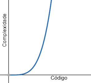
A model is an abstraction of the real world. When modeling something, we intentionally ignore irrelevant details or those that could introduce ambiguity. Therefore, a model is a simplified representation of a real system.
Models allow problems to be understood, evaluated, and critiqued in order to develop effective solutions. To build a model, a modeling language is required.
The Object Management Group (OMG) is the official organization responsible for UML standardization. Its goal is to consolidate efforts around a platform-independent approach known as Model-Driven Architecture (MDA).
UML is the language used to describe key MDA standards through the Meta-Object Facility (MOF). MOF is the metamodel that defines the concepts used to construct other models. [^PENDER,2003]
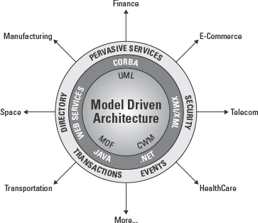
Figure. Model-Driven Architecture (MDA) and its implementations.
The metamodel specifies, for example, what a class is, what it can do, its attributes and operations, and which associations may exist. A class at this level is referred to as a meta-class.
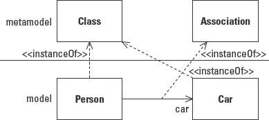
We can visualize two classes, Person and Car, as instances of these meta-classes. Instantiation in this context does not mean creating an object, but rather creating an element of the same type. Person, in the figure above, is still a class within the model—not an object.
A domain is a description of fundamental elements common to all systems within a particular subject area.
Modeling Language
A modeling language may be expressed through pseudocode, source code, or diagrams. The elements that constitute a modeling language are referred to as its notation.
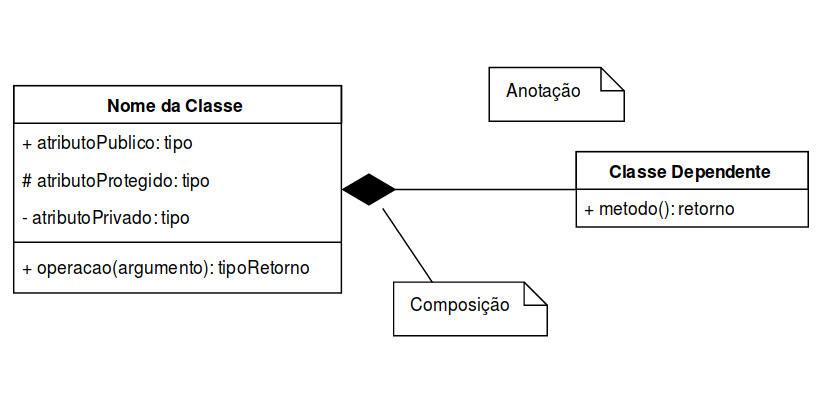
Example of a Class Diagram with two classes and annotations. The class on the right composes the class on the left.
The description of the meaning of a notation is called the semantics of the language. A modeling language consists of both notation (the means by which a model is expressed) and a description of what the notation means (a metamodel).
Some advantages of UML include:
- It is a formal language, preventing misunderstandings of the model;
- It is concise;
- It is understandable;
- It is scalable;
- It incorporates lessons learned from practice;
- It is standardized.
Natural language is ambiguous, often verbose, and lacks precise notation elements. Because it is not exact, it cannot be transformed into code in the same way a formal language can.
UML Is Not Just Diagrams
It is easy to assume UML is only about diagrams, but this is a misconception. Modeling is not merely drawing diagrams—it is about representing a system through abstractions.
Martin Fowler describes three uses of UML:
- As a sketch
- As a blueprint
- As a programming language
Modeling can be organized into four main perspectives according to Philippe Kruchten’s 4+1 View Model:
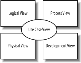
- The Logical View provides an abstract representation of the system and its parts, using class, object, state machine, and interaction diagrams.
- The Process View allows visualization of system behavior during execution, using activity diagrams.
- The Development View describes how the system is organized into modules and components, supporting architectural layering through package and component diagrams.
- The Physical View describes deployment in terms of real-world entities using deployment diagrams.
- The Use Case View describes system functionality from an external perspective and defines what the system must do, using use case diagrams.
According to their roles, UML diagrams can be classified as:
-
Structural Models
- Provide a static view of the system, like an architectural blueprint.
- Class Diagram (UML 1.x)
- Object Diagram (UML 1.x)
- Composite Structure Diagram (UML 2.x)
- Component Diagram (UML 2.x)
- Deployment Diagram (UML 1.x)
-
Behavioral Models
- Use Case Diagram (UML 1.0)
- Activity Diagram (UML 1.x)
- Interaction Diagram (UML 2.0)